System
From the outset, it was the intention for the application to be able to run in both windowed mode and full-screen mode (i.e. the application covers the entire desktop, hiding all other running applications). Games generally run in full-screen mode for a fully immersive experience, however this requires a separate monitor or a remote debugger for debug purposes so it is advantageous for the application to be able to run in both. When in full-screen mode, the code must be able to handle the different aspect ratios (typically 4:3 for standard SVGA or 16:9 for wide screen) as well as handle being resized in windowed mode.

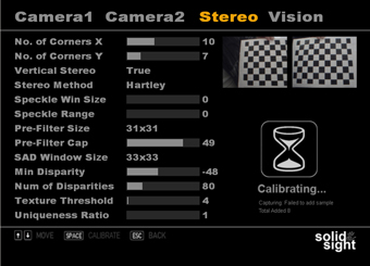
Fig 1. Screenshot from menu system which allows user to configure cameras
As the computer vision is notoriously susceptible to changes in lighting conditions, it was deemed to be important to allow the end-user to be able to configure each of the two cameras and any of the various other properties within the OpenCV setup which were important. Figure 1 shows the camera properties that can be altered via the menu system. These in turn are saved to an XML file stored locally so that when the application is started again these settings can be loaded up and applied to the specific camera. I decided to create my own menu system and custom controls using DirectX. The look and feel of the menu system was inspired by the menu system of the game GTA 4.
Stereo calibration depends on finding the rotation matrix and translation vector between the two cameras. The system uses multiple views of a planar object, a chessboard to calibrate the cameras. Using a pattern of alternating black and white squares, ensures that there is no bias toward one side or the other in measurement. Figure 2 shows the part of menu system used for this calibration with a person holding a chessboard image up to both cameras in the stereo setup. Stereo correspondence, matching a 3D point in the two different camera views can be computed only over the visual areas in which the views of the two cameras overlap.

Fig 2. Menu for Stereo Calibration and Configuration of the Disparity Map

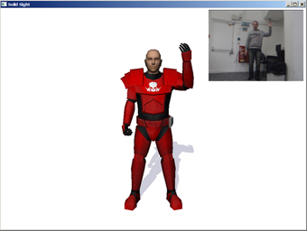
Fig 3. Left Arm Lifted of Model with insert of image captured by cameras

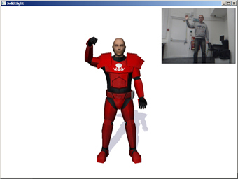
Fig 4. Right Arm Lifted of Model with insert of image captured by cameras

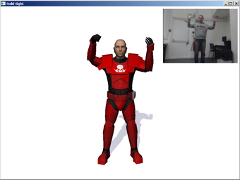
Fig 5. Both Arms of Model Lifted with insert of image captured by cameras
Figures 3 to 5 shows the system once calibrated working in even light, the photos have been overlaid over the screenshots for illustrative purposes.
Further Information
Further information is available by downloading my thesis (click here to download) or by visiting my development blog (click here to visit) which I kept during the development of this project.