Feb. 11, 2004
Publications in Graphics on the use of Skeletons for Shape Reconstruction and Animation :
BibTeX references.
Fu-Che Wu, Wan-Chun Ma, Ping-Chou Liou, Rung-Huei Laing, Ming Ouhyoung
Computer Graphics Workshop 2003, Hua-Lien, Taiwan
Wan-Chun Ma, Fu-Che Wu, Ming Ouhyoung
Shape Modeling International ( SMI'03), May 2003, Seoul, Korea
Skeleton is a lower dimensional shape description of an object. The requirements of a skeleton differ with applications. For example, object recognition requires skeletons with primitive shape features to make similarity comparison. On the other hand, surface reconstruction needs skeletons which contain detailed geometry information to reduce the approximation error in the reconstruction process. Whereas many previous works are concerned about skeleton extraction, most of these methods are sensitive to noise, time consuming, or restricted to specific 3D models.
A practical approach for extracting skeletons from general 3D models using radial basis functions (RBFs) is proposed. Skeleton generated with this approach conforms more to the human perception. Given a 3D polygonal model, the vertices are regarded as centers for RBF level set construction. Next, a gradient descent algorithm is applied to each vertex to locate the local maxima in the RBF; the gradient is calculated directly from the partial derivatives of the RBF. Finally, with the inherited connectivity from the original model, local maximum pairs are connected with links driven by the active contour model (snake). The skeletonization process is completed when the potential energy of these links is minimized.
Color plates:
J. P. Lewis, Matt Cordner & Nickson Fong
Proceedings of the 27th annual conference on Computer graphics and interactive techniques table of contents
Pages: 165 - 172, SIGGRAPH 2000
Pose space deformation generalizes and improves upon both shape interpolation and common skeleton-driven deformation techniques. This deformation approach proceeds from the observation that several types of deformation can be uniformly represented as mappings from a pose space, defined by either an underlying skeleton or a more abstract system of parameters, to displacements in the object local coordinate frames. Once this uniform representation is identified, previously disparate deformation types can be accomplished within a single unified approach. The advantages of this algorithm include improved expressive power and direct manipulation of the desired shapes yet the performance associated with traditional shape interpolation is achievable. Appropriate applications include animation of facial and body deformation for entertainment, telepresence, computer gaming, and other applications where direct sculpting of deformations is desired or where real-time synthesis of a deforming model is required
Serge Pontier,
Behzad Shariat & Denis Vandorpe (LIGIM)
Proceedings of Computer Graphics International 1998, IEEE Press,
University of Hannover, Germany, pp 583-586, June 1998.
In this paper a new method, using skeleton-based implicit model, is introduced for shape reconstruction of objects from a set of data points organized in parallel sections. To reduce complexity and computation time, the objects are described by a uniform field function and a "3D weighted skeleton". The 3D skeleton is composed of planar elements and is deduced from the 2D Voronoi skeleton of each section. The weigths are distances creating a non uniform offset of the skeleton.
Serge Pontier,
Behzad Shariat & Denis Vandorpe (LIGIM)
Proceedings of the 8th ICECGDG, Austin, Texas, USA, pp 520-525, 31 July
- 3 August 1998.
In this paper, a method is proposed to reconstruct the shape of deformable objects from 2D parallel sections. For this, we use the skeleton-based implicit model, which defines objects with a skeleton and a set of field functions. To simplify the computation, in our methodology only one field function is associated with the totality of the skeleton. To reconstruct complex shapes, this function is combined with a weighted skeleton composed of triangles whose vertices are weighted in function of a distance. These weights define a non uniform offset of the skeleton which gives a coarse description of the object. The skeleton itself is automatically deduced from the 2D Voronoi skeletons of the sections.
By C.van Overveld & B.Wyvill
Jour.
of Visualization & Computer Animation, vol.8(1), pp.3-16, 1997.
Goal : Designing 3D free-form polyhedral objects.
Solution : Polygonal skeleton consisting of a few geometrical primitives which can be interpreted as a distribution of (electrical) charges in space; the equi-potential surfaces at a given fixed potential value for a geometrical object. Each polygon of the skeleton is annotated with 2 (possibly different) extrusion distances.
Disadvantages of Implicit Surfaces Modeling (ISM) for this task :
Requirements to deriving closed manifold models (in 3D) from simple piecewise polygonal skeletons:
Different steps are possible, increasing in complexity but leading to better results. These steps are illustrated via a human figure, in Fig.1.
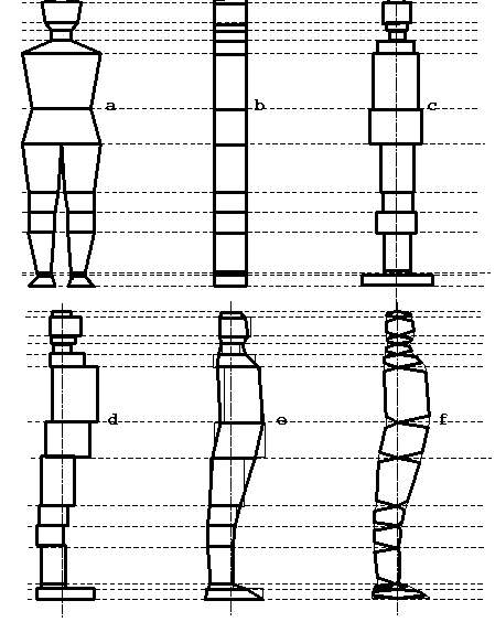
Figure 1 : (a) Original figure - front. (b) Uniform extrusion.
(c) non-uniform extrusion.
(d) non-uniform 2-sided extrusion. (e) Cº non-uniform 2-sided
extrusion.
(f) Trapezoidal Cº non-uniform 2-sided extrusion.
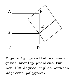
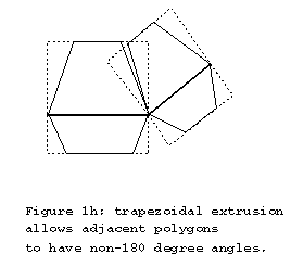
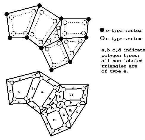
Figure 2 : Top - A polygon mesh before applying subdivision.
Bottom - After subdivision.
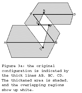
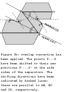
Self-intersection cannot be avoided globally with the proposed method. On a local basis, however, one can define "safe" regions bordered by separator planes, such that most self-intersection can be avoided. This is illustrated in Fig.3.
For an edge with more than 2 incident edges, a more elaborate approach is required; it consists of 4 phases. This is illustrated in Fig.4.
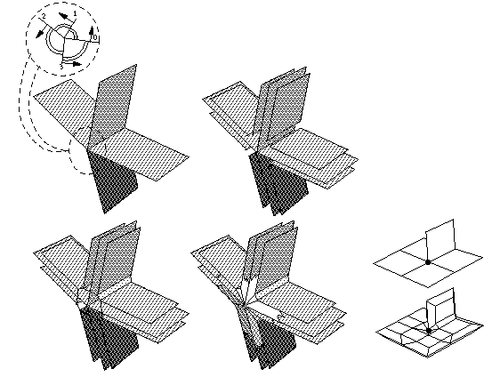
Figure 4 : The four phases of the mesh computation for a
non-manifold edge.
Upper-left: the incident faces are sorted on increasing angle with a
reference face, and normal vectors are oriented accordingly.
Upper-right: for each incident face, 2 offset faces are computed.
Lower-left: offset face `UP' for incident face i is connected with
offset face `DOWN' for incident face i+1, and cyclic.
Lower-right: the remaining triangular holes are filled.
Inset: as a consequencem the marked point will occur in the resulting
mesh.
There are still 2 cases which can be problematical:
Table 1 below summarizes the comparison between the 2 methods.
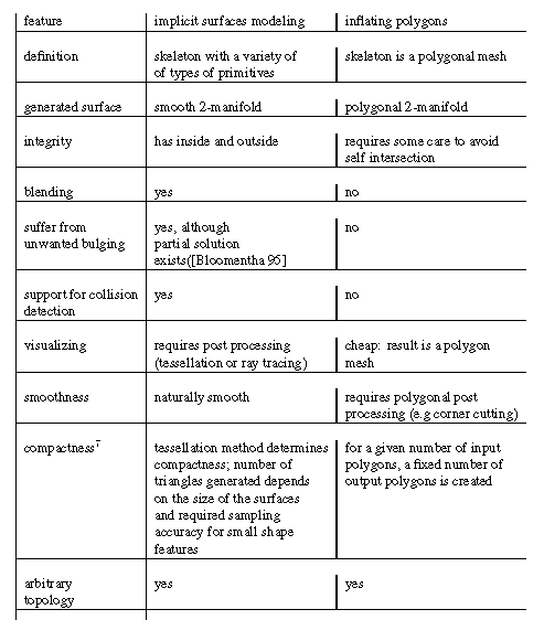
The computational complexity of polygon inflation is proportional to the number of generated polygons, which in practice seems to be an order of magnitude lower than with ISM techniques, for a similar accuracy (of the resulting 3D mesh). Interactive manipulation of the skeleton vertices and change of the extrusion distance is directly available. Topological changes however remain difficult as they require the calculation ot the mesh topology.
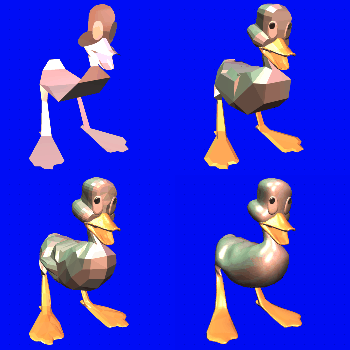
To illustrate the usefuulness of the proposed modelling technique, which starts from simple polygon skeletons and derives a full 3-D polygon mesh from them, see Fig. 5 & 6.
|
|
(a) Non-manifold polygon mesh. |
(b) Duck-shape. |
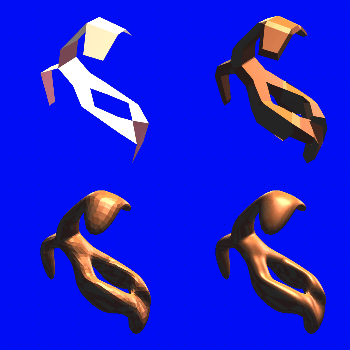
Figure 6 : Comparison of Polygonal Skeleton Inflation
with ISM.
Upper left: the skeleton. Upper right: the result from polygon
inflation, mesh subdivision and smooth shading. On the bottom row, two
attempts are depicted to sample the associated implicit surface with a
regular grid of voxels: left, low resolution; right, high resolution.
Page created & maintained by Frederic Leymarie,
1998-2004.
Comments, suggestions, etc., mail to: leymarie@lems.brown.edu