
Last update: Aug. 31, 1998
Publications on Radiosity for Light Rendering :
BibTeX references.
* Adapted from notes of P.J.Willis@bath.ac.uk .
Short definition of Radiosity::
Simple rendering and lighting techniques do not allow for the interchange of light energy between surfaces in a scene. A radiosity calculation for a given scene is one which, starting from an assumption of energy equilibrium, calculates (approximately) how much energy is being reflected from any given surface, due to all other surfaces interchanging energy with it.
This allows for softer lighting effects, colour bleeding from one surface to another and non point-source lighting. Two important features of the approach are that light sources are treated the same as all other areas of the scene exept that they have a positive initial emission; and the radiosity equations are solved before rendering the picture (using a Gouraud technique). Hence, there is a very slow initial calculation but multiple views of the same scene can be produced rapidly. Radiosity is thus part of surface rendering. It is used with mesh models.
Imagine a closed 3D model, perhaps the interior of a room containing a number of objects of furniture, illuminated by several light panels. The room is in a state of energy equilibrium in the sense that, for any given part of the scene other than the lights themselves, the energy reaching it is equal to that absorbed plus that scattered. Furthermore, the scattered light itself becomes a fraction of the light reaching some other parts of the scene. Finally the total output of the lights must eventually be scattered towards the eye or absorbed.
In principle we would like to solve this equilibrium for all parts of the scene, then it is trivially easy to render the picture. If we really could do this, then we would have all the soft-edged lighting effects of a real room. In practice, this is asking far too much, so we approximate the interior to a series of patches, assumed to be energetically uniform. We then calculate all possible interchanges between each patch and all of the others, to arrive at an energy value for that one patch. We repeat this for all other patches. Finally we render the scene Gouraud style, in order to blend across the boundaries of the patches. One particular benefit of this approach is that lights can be any shape, modelled from patches.
Radiosity is the sum of the emitted energy component (if it is a light source patch) and the reflected (coming in from other patches). At energy equilibrium we can therefore write:

where:
In effect, Bj dAj , is the radiosity leaving j and is
that part of it which reaches (`is visible at') patch i. As
we have equilibrium, there is a reciprocity relationship:  .
.
Therefore, converting to the more tractable discrete form, we have

Such an equation must apply to every surface patch in the model, so the complete model is solved from a system of n simultaneous equations, the so-called "full matrix" radiosity solution :
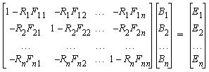
Strictly, we have shown a monochromatic solution: we have to use at least three sets of the above if we want full colour (say for the RGB channels). This is not a computationally cheap method! The emissivities, Ei , are zero except at light-emitting patches. These terms are the total energy entering the (closed) system. The reflection coefficients, Ri , are known from the surface characteristics (e.g. the BRDF data). The form factors, Fi , have to be calculated from the geometry. For plane or convex surfaces, none of the energy leaving a surface hits itself, so Fii = 0 . Calculating the form factors is the time-intensive part.
A numerical method for calculating form-factors, the Hemicube method, was published in 1985, by Cohen & Greenberg. We imagine an elemental area on patch i which has a hemispherical view of the environment. We project the other patches onto this hemisphere and use these projections to calculate the form factor.
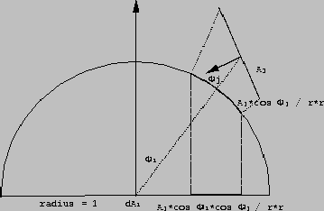
Figure 1. Estimating the form factor: the hemicube method
Let us consider the form factor between elemental area dAi (at the centre of patch i, which we treat as the `average' position of patch i ) and the finite area Aj . We then approximate (see Fig. 1):

To evaluate this integral we introduce another approximation that the hemisphere can be replaced by a hemicube. In other words by half a unit box. We do this because it is much easier to project onto planes than onto the sphere (!). Furthermore, we divide the outer surface into small cells: the more cells the better the accuracy but the more computation. Certainly we will use hundreds. We project all other patches in turn onto the hemicube. Some patches will project entirely onto one face of the hemicube, others will fall on more. We cope with this by first clipping the patches against the hemicube geometry, then projecting the clipped parts onto their corresponding hemicube face. Where one cell is covered by more than one patch, we choose the nearest (z-buffer method) and record which it is. In other words, the cells are really an item buffer.
The contributions of each cell are weighted differently. For example, the cell directly above the centre can be `seen' square-on from the centre. In contrast, a cell on the top face but close to the edge of the cube can only be seen obliquely. Hence there is a form-factor due to this which must be used to weight the projections on to the cells. These `delta' form-factors can be precomputed and there is plenty of symmetry to reduce the computation.
At the end of all this, we have produced a mesh approximation to the 3D scene, with the radiosity values all known. We can now choose a viewpoint and use Gouraud shading to blend the patches together. We can see the model from other viewpoints without repeating the radiosity calculations.
The largest single advantage of the radiosity method for computer image generation is the highly realistic quality of the resulting images. No other method accurately calculates the diffuse interreflection of light energy in an environment. Soft shadows and color bleeding are natural by-products of this method, just as hard shadows and mirror-like reflections are natural by-products of a typical ray-tracing algorithm.
In addition to being visually pleasing, the method can be quite accurate in its treatment of energy transport between surfaces.
The viewpoint independence of the basic radiosity algorithm provides the opportunity for interactive "walkthroughs" of environments, as one intensity solution for an environment will serve as the base for any particular view of the environment.
The costs associated with the radiosity method are substantial. The "full matrix" radiosity method requires a large amount of storage and long computation times for form factor calculation and matrix solution. The "progressive" method must also calculate a large number of form factors, many more than once.
Accuracy in the resulting intensity solution requires preprocessing the environment, subdividing large surfaces into a set of smaller surfaces, and more surfaces means more storage and computation.
by Akio Doi
and Takayuki Itoh
Jour.
of Visualization & Computer Animation, vol.9(1), pp.3-15, 1998.
Most of the computation time for radiosity image synthesis is spent calculating the formfactors for a large number of patches, and more precise and rapid formfactor calculation methods are needed. In our rendering system, we propose a hemisphere-base projection method for calculating formfactors, which is an improved version of Spencer's and Van Wyk's methods. These 2 methods fail to remove hidden surfaces for relatively large patches and cause large discretization errors in formfactors. We have also developed an interactive and rapid image synthesis system.
3 basic approaches are used:
Analytical solution and ray-tracing permit precise calculation of form factors but with relatively high computational costs.
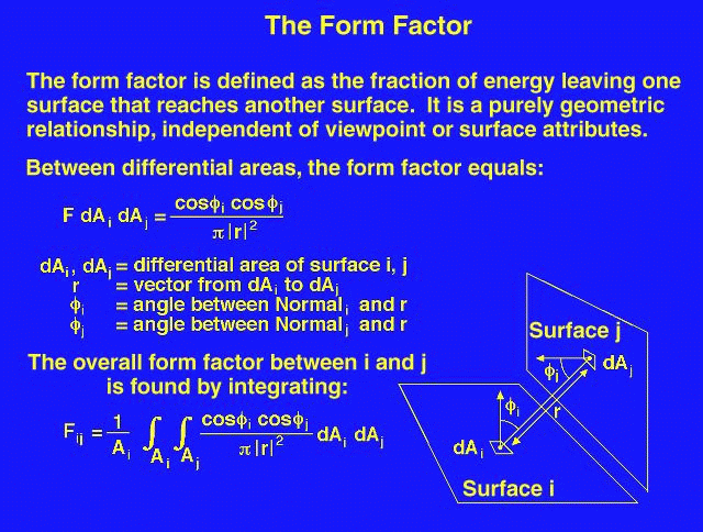
In practice, the form factor between 2 finite surfaces is re-defined as:

where HID is a binary flag set to 1 or 0 depending on whether dAj is visible or not from dAi .
Hemi-space projection methods are further classified, according to the type of projection, into:
Differentiation of the basic form factor equation is difficult even for simple surfaces. The "hemicube" form factor calculation method involves placing the center of a cube at a point on a surface, and using the upper half of the cube (the "hemicube" which is visible above the surface) as a projection body. Each face of the hemicube is subdivided into a set of small, usually square ("discrete") areas, each of which has a pre-computed form factor value. When a surface is projected onto the hemicube, the sum of the form factor values of the discrete areas of the hemicube faces which are covered by the projection of the surface is the form factor between the point on the first surface (about which the cube is placed) and the second surface (the one which was projected).
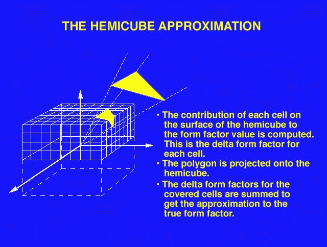
The speed and accuracy of this method of form factor calculation can be affected by changing the size and number of discrete areas on the faces of the hemicube.
The delta form factors are defined as follows :  .
.
The "Nusselt analog" involves placing a hemispherical projection body, with unit radius, at a point on a surface. The second surface is spherically projected onto the projection body, then cylindrically projected onto the base of the hemisphere. The form factor is, then, the area projected on the base of the hemisphere divided by the area of the base of the hemisphere.
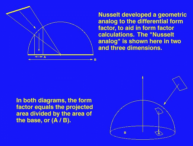
Advantages of Nusselt's analogue:
Spencer and van Wyck have proposed hemisphere-base methods of projection with edge subdivision. They calculate the degree of arc between pairs of points projected onto a hemisphere base. This value is used to determine a number of intermediate points along the element's edge.
This method has the following drawback that, when the area projected onto a hemisphere's base is large, the edge subdivision process fails to remove certain hidden surfaces. Such situations are quite common in practice, e.g. consider the case of books on a table.
Instead or merely generating intermediate points on edges, a surface element is subdivided into small trianglular patches. A solid angle criterion is used to guarantee accuracy; when the angle is larger than the user tolerance, recursive triangulation is applied.
Page created & maintained by Frederic Leymarie,
1998.
Comments, suggestions, etc., mail to: leymarie@lems.brown.edu